Ideal location for critical section of a plastic hinges:
1. Beam – to – column connection: not less than a distance hb (beam depth) from the connection.
2. Column – to – beam connection: at anywhere within the beam length, between column faces.
3. Beam – to – beam connection: not less than a distance hb (beam depth) from the connection.
4. Column – to – column connection: at anywhere within the beam length, between column faces
5. Column – to – footing connection: not less than a distance hc (column width in the direction considered) from the connection.
Location for ductile connection:
1. In beams – at any location. But it is better to locate it as close as possible to the columns
2. At column bases – to complete mechanism
Requirements for Special Moment Frames with Strong Connections
- Shall satisfy all requirements for SRPMK
- Segments between locations where flexural yielding is intended to occur follow bernoulli princpl (min 4 times h)
- Design strength of the strong connection fSn shall be not less than Se
- Primary long rebars shall be made continuous across connections and shall be developed outside both the strong connection and the plastic hinge region.
- Column-to-column connections shall have design strength fSn not less than 1.4Se, the design flexural strength fMn not less than 0.4 times the maximum probable flexural strength Mpr for the column within the story height, and the design shear strength fVn of the connection shall be not less than that determined by Mpr .
SRPM with ductile connection constructed using precast concrete shall satisfy the following requirements and other requirement for SRPMK:
- The nominal shear strength for connections, Vn , shall be greater than or equal to 2Ve, and
- Mechanical splices of beam reinforcement shall be located not closer than h/2 from the joint face
Emulation Design
- Based on SNI Concrete code chapter 23.2.1.5:
1. The system will have strength and toughness equal to or exceeding those provided by a comparable monolithic reinforced concrete structure
- Procedures
1. Design the structure as if it is to be constructed by monolithic cast in place reinforced concrete methods.
2. Disassemble the structure “on paper” into appropriate sizes and shapes to meet the following criteria, i.e. suitable for plant fabrication, capable of being transported and can be erected by the available cranes.
3. Design the connection:
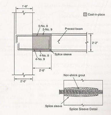
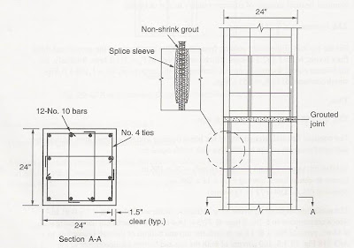
· connect rebars between the precast elements by mechanical splices, welding the rebars, or by grouting the conduit or sleeves with high-strength, non shrink grout
· connect the precast concrete elements using a high-strength, non shrink grout in the interfaces or by placing conventional concrete in the spaces between the precast elements.
Emulation Details
- Reinforcing steel splicing is accomplished in the same manner as in cast – in – place – concrete by:
1. Lapping
2. Welding
3. Joining with mechanical splices
- SNI Specification
1. Connect the reinforcing bars by mechanical splices, welding, grouting or sleeves with high-strength and non-shrink grout.
2. Both welded and mechanical splices must achieve strengths of at least 125 percent of rebar yield strength, fy.
3. For lapped splices refers to chapter 14 of SNI Concrete Code
4. The bar size determines the size of connection device
5. Staging of the erection should be considered in design
CONNECTION MADE BY GROUTING OF PRECAST CONCRETE COMPONENTS
- When cement-based grouts are used they should be high strength and non-shrink. The minimum grout compressive strength should be 10 MPa greater than that of the surrounding concrete.
- For all grouting situations, extreme thoroughness with respect to cleanliness and the following of manufacturer’s instructions is required.
- When bars are grouted in horizontal or inclined holes, bar locaters should be used to keep the bars in the center of the holes.
- Designers should communicate to contractors at tender stage all the specialized requirements for the grouting operations, including the need for experienced operators and a satisfactory quality assurance programme.
- The grout volume method should be used to determine whether or not the units have been fully grouted.
- Before compressed air is used to blow out dust from holes, it should be tested for oil contamination.
Preferable Behaviour of Precast System
- Behaviour of Precast System @ Behaviour of Monolithic System
- Structural Element Yield Under Bending Type of Failure
- Beam Yield First
- Slip And Shear Mechanisms Do Not Dominate the Behaviour
- Shows Stable Hysteretic Behaviour
Example of Strong Beam to Column Connection
Example of Strong Column to Column Connection


Tidak ada komentar:
Posting Komentar